
I asked a while ago, how to build an automatic light switch and finally got around to actually building it.
My board is an ESP8266 mini D, and ignoring all the sensor parts, my problem right now is powering the actual light.
It’s just a small LED array and I connected it directly to the 5V and GND pins (controlled via a transistor).
Measuring from the wall (so including the PSU), this whole setup pulls about 3W (so far expected), however, one small component close to the USB connector gets uncomfortably warm, and I’m not sure, whether that’s ok.
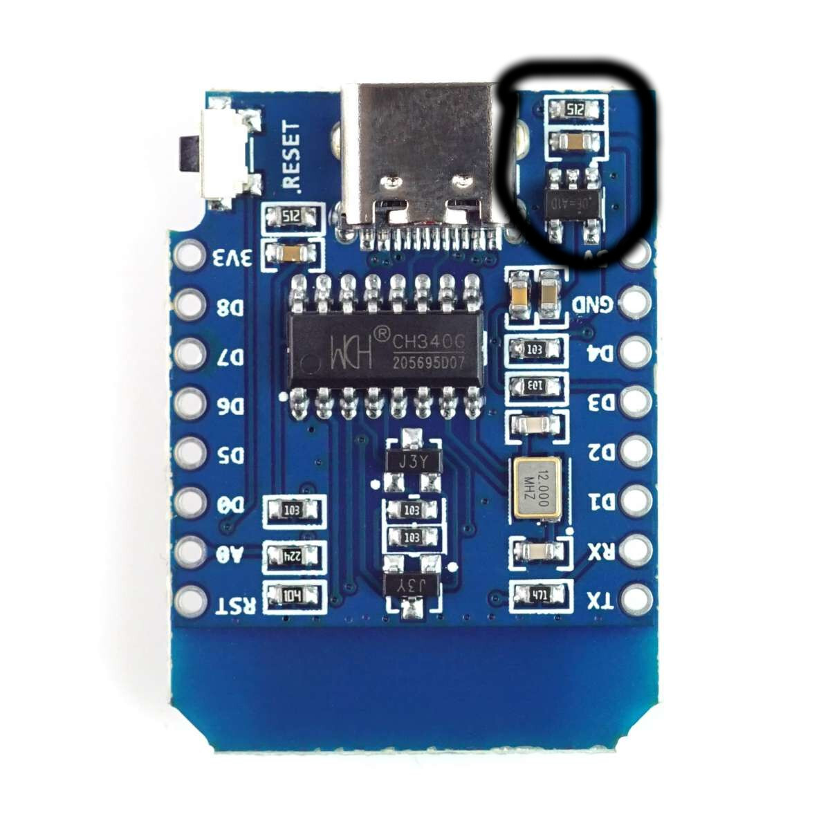
The hot component is one of the two small thingies circled in the picture. I thought the 5V get pulled directly from the USB plug, so I’m not sure, why there is any circuitry involved.
It helps ensure that levels between 2.5v and 5.5v can be fed to the controller without breaking anything. For some cheaper power supplies you might get a voltage drop when starting to pull load, this will clean that up and prevent the voltage from dropping too low for the microcontroller.
If I’m reading the correct datasheet I can see it is current limiting so it should shutdown when overdrawn.